In 1834, German physicist Heinrich Friedrich Lenz (1804-1865) deduced a rule, known as Lenz’s law which gives the polarity of the induced emf in a clear and concise fashion. The statement of the law is:
The polarity of induced emf is such that it tends to produce a current which opposes the change in magnetic flux that produced it.
The negative sign shown in Eq. (6.3) represents this effect. We can understand Lenz’s law by examining Experiment 6.1 in Section 6.2.1. In Fig. 6.1, we see that the North-pole of a bar magnet is being pushed towards the closed coil. As the North-pole of the bar magnet moves towards the coil, the magnetic flux through the coil increases. Hence current is induced in the coil in such a direction that it opposes the increase in flux. This is possible only if the current in the coil is in a counter-clockwise direction with respect to an observer situated on the side of the magnet. Note that magnetic moment associated with this current has North polarity towards the North-pole of the approaching magnet. Similarly, if the North-pole of the magnet is being withdrawn from the coil, the magnetic flux through the coil will decrease. To counter this decrease in magnetic flux, the induced current in the coil flows in clockwise direction and its South-pole faces the receding North-pole of the bar magnet. This would result in an attractive force which opposes the motion of the magnet and the corresponding decrease in flux.
What will happen if an open circuit is used in place of the closed loop in the above example? In this case too, an emf is induced across the open ends of the circuit. The direction of the induced emf can be found using Lenz’s law. Consider Figs. 6.6 (a) and (b). They provide an easier way to understand the direction of induced currents. Note that the direction shown by  and
and  indicate the directions of the induced currents.
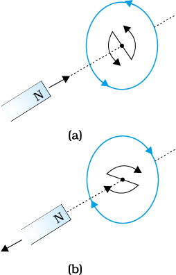
Figure 6.6 Illustration of Lenz’s law.
A little reflection on this matter should convince us on the correctness of Lenz’s law. Suppose that the induced current was in the direction opposite to the one depicted in Fig. 6.6(a). In that case, the South-pole due to the induced current will face the approaching North-pole of the magnet. The bar magnet will then be attracted towards the coil at an ever increasing acceleration. A gentle push on the magnet will initiate the process and its velocity and kinetic energy will continuously increase without expending any energy. If this can happen, one could construct a perpetual-motion machine by a suitable arrangement. This violates the law of conservation of energy and hence can not happen.
Now consider the correct case shown in Fig. 6.6(a). In this situation, the bar magnet experiences a repulsive force due to the induced current. Therefore, a person has to do work in moving the magnet. Where does the energy spent by the person go? This energy is dissipated by Joule heating produced by the induced current.
Example 6.4
Figure 6.7 shows planar loops of different shapes moving out of or into a region of a magnetic field which is directed normal to the plane of the loop away from the reader. Determine the direction of induced current in each loop using Lenz’s law.
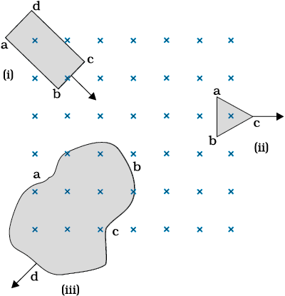
Figure 6.7
Solution
(i) The magnetic flux through the rectangular loop abcd increases, due to the motion of the loop into the region of magnetic field, The induced current must flow along the path bcdab so that it opposes the increasing flux.
(ii) Due to the outward motion, magnetic flux through the triangular loop abc decreases due to which the induced current flows along bacb, so as to oppose the change in flux.
(iii) As the magnetic flux decreases due to motion of the irregular shaped loop abcd out of the region of magnetic field, the induced current flows along cdabc, so as to oppose change in flux.
Note that there are no induced current as long as the loops are completely inside or outside the region of the magnetic field.
Example 6.5
(a) A closed loop is held stationary in the magnetic field between the north and south poles of two permanent magnets held fixed. Can we hope to generate current in the loop by using very strong magnets?
(b) A closed loop moves normal to the constant electric field between the plates of a large capacitor. Is a current induced in the loop
(i) when it is wholly inside the region between the capacitor plates (ii) when it is partially outside the plates of the capacitor? The electric field is normal to the plane of the loop.
(c) A rectangular loop and a circular loop are moving out of a uniform magnetic field region (Fig. 6.8) to a field-free region with a constant velocity v. In which loop do you expect the induced emf to be constant during the passage out of the field region? The field is normal to the loops.
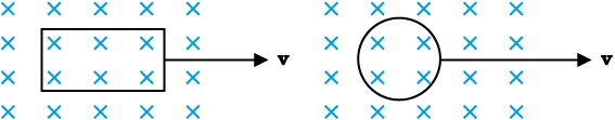
Figure 6.8
(d) Predict the polarity of the capacitor in the situation described by Fig. 6.9.
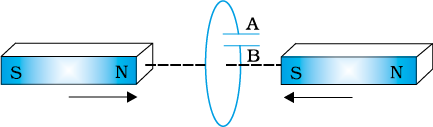
Figure 6.9
(a) No. However strong the magnet may be, current can be induced only by changing the magnetic flux through the loop.
(b) No current is induced in either case. Current can not be induced by changing the electric flux.
(c) The induced emf is expected to be constant only in the case of the rectangular loop. In the case of circular loop, the rate of change of area of the loop during its passage out of the field region is not constant, hence induced emf will vary accordingly.
(d) The polarity of plate ‘A’ will be positive with respect to plate ‘B’ in the capacitor.
© 2026 GoodEd Technologies Pvt. Ltd.

