The figure shows a logic circuit with two inputs \(A\) and \(B\) and the output \(C\). The voltage waveforms across \(A\), \(B\), and \(C\) are as given. The logic circuit gate is:
   

1. \(\text{OR}\) gate
2. \(\text{NOR}\) gate
3. \(\text{AND}\) gate
4. \(\text{NAND}\) gate

Subtopic:  Logic gates |
 83%
From NCERT
AIPMT - 2012
To view explanation, please take trial in the course.
NEET 2025 - Target Batch
Hints
To view explanation, please take trial in the course.
NEET 2025 - Target Batch

\(\mathrm{p\text-n}\) photodiode is fabricated from a semiconductor with a band gap of \(2.5\) eV. It can detect a signal of wavelength:
1. \(6000~\mathring{A}\)
2. \(4000\) nm
3. \(6000\) nm
4. \(4000~\mathring{A}\)  
Subtopic:  Energy Band theory |
 63%
From NCERT
AIPMT - 2009
To view explanation, please take trial in the course.
NEET 2025 - Target Batch
Hints
To view explanation, please take trial in the course.
NEET 2025 - Target Batch

The circuit is equivalent to: 
 The circuit is equivalent to | Physics Questions

1. AND gate
2. NAND gate
3. NOR gate
4. OR gate

Subtopic:  Logic gates |
 75%
From NCERT
AIPMT - 2008
To view explanation, please take trial in the course.
NEET 2025 - Target Batch
Hints
To view explanation, please take trial in the course.
NEET 2025 - Target Batch

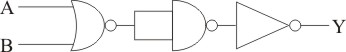
In the following circuit, the output \(Y\) for all possible inputs \(A\) and \(B\) is expressed by the truth table: 
    

1.
\(A\) \(B\) \(Y\)
\(0\) \(0\) \(0\)
\(0\) \(1\) \(0\)
\(1\) \(0\) \(0\)
\(1\) \(1\) \(1\)
2.
\(A\) \(B\) \(Y\)
\(0\) \(0\) \(1\)
\(0\) \(1\) \(1\)
\(1\) \(0\) \(1\)
\(1\) \(1\) \(0\)
3.
\(A\) \(B\) \(Y\)
\(0\) \(0\) \(1\)
\(0\) \(1\) \(0\)
\(1\) \(0\) \(0\)
\(1\) \(1\) \(1\)
4.
\(A\) \(B\) \(Y\)
\(0\) \(0\) \(0\)
\(0\) \(1\) \(1\)
\(1\) \(0\) \(1\)
\(1\) \(1\) \(1\)
Subtopic:  Logic gates |
 75%
From NCERT
AIPMT - 2007
To view explanation, please take trial in the course.
NEET 2025 - Target Batch
Hints
To view explanation, please take trial in the course.
NEET 2025 - Target Batch

\({C}\) and \({Si}\) both have the same lattice structure, having \(4\) bonding electrons in each. However, \(C\) is an insulator whereas \(Si\) is an intrinsic semiconductor. This is because:
1. in the case of \(C\), the valence band is not completely filled at absolute zero temperature.
2. in the case of \(C\), the conduction band is partly filled even at absolute zero temperature.
3. the four bonding electrons in the case of \(C\) lie in the second orbit, whereas in the case of \(Si\), they lie in the third.
4. the four bonding electrons in the case of \(C\) lie in the third orbit, whereas for \(Si\), they lie in the fourth orbit.
Subtopic:  Energy Band theory |
 71%
From NCERT
NEET - 2012
To view explanation, please take trial in the course.
NEET 2025 - Target Batch
Hints
To view explanation, please take trial in the course.
NEET 2025 - Target Batch

To get output \(Y=1\) for the following circuit, the correct choice for the input is:
  

1. \(A=1,~ B= 0, ~C=0\)
2. \(A=1,~ B= 1, ~C=0\)
3. \(A=1,~ B= 0, ~C=1\)
4. \(A=0,~ B= 1, ~C=0\)

Subtopic:  Logic gates |
 89%
From NCERT
NEET - 2016
To view explanation, please take trial in the course.
NEET 2025 - Target Batch
Hints
To view explanation, please take trial in the course.
NEET 2025 - Target Batch

The given electrical network is equivalent to:
   

1. \(\text{OR}\) gate 2. \(\text{NOR}\) gate
3. \(\text{NOT}\) gate 4. \(\text{AND}\) gate
Subtopic:  Logic gates |
 73%
From NCERT
NEET - 2017
To view explanation, please take trial in the course.
NEET 2025 - Target Batch
Hints
To view explanation, please take trial in the course.
NEET 2025 - Target Batch

Zener breakdown will occur if:
1. impurity level is low.
2. impurity level is high.
3. impurity is less on the \(\mathrm{n\text-}\)side.
4. impurity is less on the \(\mathrm{p\text-}\)side.

Subtopic:  Applications of PN junction |
 75%
From NCERT
To view explanation, please take trial in the course.
NEET 2025 - Target Batch
Hints
To view explanation, please take trial in the course.
NEET 2025 - Target Batch

The logic behind the 'NOR' gate is that it gives:

1. High output when both the inputs are low.
2. Low output when both the inputs are low.
3. High output when both the inputs are high.
4. None of these

Subtopic:  Logic gates |
 85%
From NCERT
To view explanation, please take trial in the course.
NEET 2025 - Target Batch
Hints
To view explanation, please take trial in the course.
NEET 2025 - Target Batch

In a transistor circuit shown here, the base current is  35 μA  and the potential difference across emitter-base junction is 4.5 V. The value of the resistor Rb is:
                 

1. 128.5 kΩ

2. 257 kΩ

3. 380.05 kΩ

4. None of these

Subtopic:  Applications of Transistor (OLD NCERT) |
 81%
From NCERT
To view explanation, please take trial in the course.
NEET 2025 - Target Batch
Hints
To view explanation, please take trial in the course.
NEET 2025 - Target Batch