
 Q. No.
The metre bridge shown is in a balanced position with \(\frac{P}{Q} = \frac{l_1}{l_2}\). If we now interchange the position of the galvanometer and the cell, will the bridge work? If yes, what will be the balanced condition?

1. Yes, \(\frac{P}{Q}=\frac{l_1-l_2}{l_1+l_2}\)
2. No, no null point
3. Yes, \(\frac{P}{Q}= \frac{l_2}{l_1}\)
4. Yes, \(\frac{P}{Q}= \frac{l_1}{l_2}\)
1. Yes, \(\frac{P}{Q}=\frac{l_1-l_2}{l_1+l_2}\)
2. No, no null point
3. Yes, \(\frac{P}{Q}= \frac{l_2}{l_1}\)
4. Yes, \(\frac{P}{Q}= \frac{l_1}{l_2}\)


Figure \((a)\) below shows a Wheatstone bridge in which \(P,Q,R,S\) are fixed resistances, \(G\) is a galvanometer, and \(B\) is a battery. For this particular case, the galvanometer shows zero deflection. Now, only the positions of \(B\) and \(G\) are interchanged. as shown in figure \((b).\) The new deflection of the galvanometer:

| 1. | is to the left |
| 2. | is to the right |
| 3. | is zero |
| 4. | depends on the values of \(P,Q,R,S\) |
| 1. | more than \(1\) kW |
| 2. | less than \(1\) kW but not zero |
| 3. | \(1\) kW |
| 4. | \(0\) |


A student has three \(6.0~\Omega\) resistors that can be connected together in any configuration. What are the maximum and minimum resistance that can be obtained by using one or more of these three resistors?
(Assume the connections between the resistors have negligible resistance, the temperature of the resistors is constant, and the resistors are used in a d.c. circuit and none of the resistors are shortcircuited.)
| 1. | maximum resistance: \(12~\Omega\); minimum resistance: \(0.50~\Omega\) |
| 2. | maximum resistance: \(6.0~\Omega\); minimum resistance: \(0.50~\Omega\) |
| 3. | maximum resistance: \(18~\Omega\); minimum resistance: \(6.0~\Omega\) |
| 4. | maximum resistance: \(18~\Omega\); minimum resistance: \(2.0~\Omega\) |
Three resistors are connected to a \(20\) V battery with a constant supply. One of the resistors is a variable resistor. The resistance of the variable resistor is gradually increased from zero to \(5\) \(\Omega.\)
Which graph shows how the current from the battery varies with the resistance \((R)\) of the variable resistor?

| 1. | 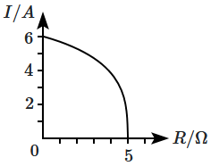 |
2. |  |
| 3. |  |
4. |  |
A torch bulb rated \(4.5\) W, \(1.5\) V is connected as shown in the figure below. The emf of the cell needed to make the bulb glow at full intensity is:

| 1. | \(4.5\) V | 2. | \(1.5\) V |
| 3. | \(2.67\) V | 4. | \(13.5\) V |
| 1. | \(2~\Omega\) | 2 | \(1~\Omega\) |
| 3. | \(0.5~\Omega\) | 4. | zero |
In the circuit shown in the figure below, the current supplied by the battery is:
1. \(2\) A
2. \(1\) A
3. \(0.5\) A
4. \(0.4\) A

The equivalent resistance between points \(A\) and \(B\) in the circuit shown in the figure is:

| 1. | \(6R\) | 2. | \(4R\) |
| 3. | \(2R\) | 4. | \(R\) |
In the circuit shown in the figure below, if the potential difference between \(B\) and \(D\) is zero, then value of the unknown resistance \(X\) is:
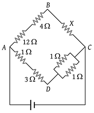
| 1. | \(4~\Omega\) | 2. | \(2~\Omega\) |
| 3. | \(3~\Omega\) | 4. | EMF of a cell is required to find the value of \(X\) |
© 2024 GoodEd Technologies Pvt. Ltd.