
 Q. No.
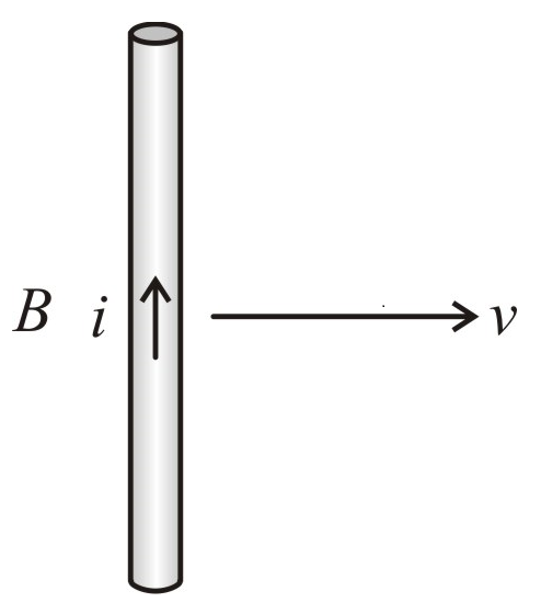
A conducting wire is moving towards the right in a magnetic field B. The direction of the induced current in the wire is shown in the figure. The direction of the magnetic field will be:
1.
In the plane of paper pointing towards the right.
2.
In the plane of paper pointing towards the left.
3.
Perpendicular to the plane of the paper and downwards.
4.
Perpendicular to the plane of the paper and upwards.


Two circuits have coefficient of mutual induction of \(0.09\) henry. Average emf induced in the secondary by a change of current from \(0\) to \(20\) ampere in \(0.006\) second in the primary will be:
1. \(120\) V
2. \(80\) V
3. \(200\) V
4. \(300\) V
In the figure magnetic energy stored in the coil is:

| 1. | Zero | 2. | Infinite |
| 3. | \(25\) joules | 4. | None of the above |


Consider the situation shown in the figure. The wire AB is sliding on the fixed rails with a constant velocity. If the wire AB is replaced by semicircular wire, the magnitude of the induced current will:

| 1. | increase. |
| 2. | remain the same. |
| 3. | decrease. |
| 4. | increase or decrease depending on whether the semicircle bulges towards the resistance or away from it. |
| 1. | directly proportional to \(i\). |
| 2. | directly proportional to \(R\). |
| 3. | directly proportional to \(R^2\). |
| 4. | Zero. |
A uniform but time-varying magnetic field \(B(t)\) exists in a circular region of radius \(a\) and is directed into the plane of the paper, as shown. The magnitude of the induced electric field at point \(P\) at a distance \(r\) from the centre of the circular region:

1. is zero
2. decreases as \(\frac{1}{r}\)
3. increases as \(r\)
4. decreases as \(\frac{1}{r^2}\)
Two circular coils can be arranged in any of the three situations shown in the figure. Their mutual inductance will be:

| 1. | maximum in the situation (A). |
| 2. | maximum in the situation (B). |
| 3. | maximum in the situation (C). |
| 4. | the same in all situations. |
A conducting rod of length \(2l\) is rotating with constant angular speed \(\omega\) about its perpendicular bisector. A uniform magnetic field \(\vec {B}\) exists parallel to the axis of rotation. The emf induced between the two ends of the rod is:

1. \(B\omega l^2\)
2. \(\frac{1}{2} B \omega l^{2}\)
3. \(\frac{1}{8} B \omega l^{2}\)
4. zero
A conductor ABOCD moves along its bisector with a velocity of \(1\) m/s through a perpendicular magnetic field of \(1~\text{wb/m}^2\), as shown in fig. If all the four sides are of \(1\) m length each, then the induced emf between points A and D is:

1. \(0\)
2. \(1.41\) volt
3. \(0.71\) volt
4. None of the above
A wire cd of length \(l\) and mass \(m\) is sliding without friction on conducting rails \(ax\) and \(by\) as shown. The vertical rails are connected to each other with a resistance \(R\) between \(a\) and \(b\). A uniform magnetic field \(B\) is applied perpendicular to the plane \(abcd\) such that \(cd\) moves with a constant velocity of:

| 1. | \({mgR \over Bl}\) | 2. | \({mgR \over B^2l^2}\) |
| 3. | \({mgR \over B^3l^3}\) | 4. | \({mgR \over B^2l}\) |
© 2024 GoodEd Technologies Pvt. Ltd.