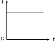
A coil having an area is placed in a magnetic field which changes from in a time interval t. The e.m.f. induced in the coil will be
1.
2.
3.
4.
A magnet NS is suspended from a spring and while it oscillates, the magnet moves in and out of the coil C. The coil is connected to a galvanometer G. Then as the magnet oscillates,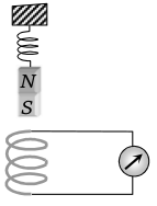
1. G shows deflection to the left and right with constant amplitude
2. G shows deflection on one side
3. G shows no deflection
4. G shows deflection to the left and right but the amplitude steadily decreases.
A rectangular coil ABCD is rotated anticlockwise with a uniform angular velocity about the axis shown in diagram, below. The axis of rotation of the coil as well as the magnetic field B, are horizontal. The induced e.m.f. in the coil would be maximum when 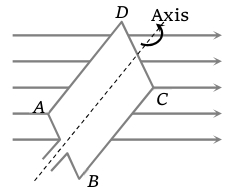
1. The plane of the coil is horizontal
2. The plane of the coil makes an angle of with the magnetic field
3. The plane of the coil is at right angles to the magnetic field
4. The plane of the coil makes an angle of with the magnetic field
An inductor, L a resistance R and two identical bulbs, and are connected to a battery through a switch S as shown in the figure. The resistance R is the same as that of the coil that makes L. Which of the following statements gives the correct description of the happenings when the switch S is closed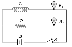
1. The bulb lights up earlier than and finally both the bulbs shine equally bright
2. light up earlier and finally both the bulb acquire equal brightness
3. lights up earlier and finally shines brighter than
4. and light up together with equal brightness all the time
A transformer is employed to reduce 220 V to 11 V. The primary draws a current of 5 A and the secondary 90 A. The efficiency of the transformer is
1. 20%
2. 40%
3. 70%
4. 90%
An electron moves along the line AB, which lies in the same plane as a circular loop of conducting wires as shown in the diagram. What will be the direction of the current if any, in the loop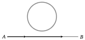
1. No current will be induced
2. The current will be clockwise
3. The current will be anticlockwise
4. The current will change direction as the electron passes by
An e.m.f. of 15 volt is applied in a circuit containing 5-henry inductance and 10 ohm resistance. The ratio of the currents at time t = and at t = 1 seconds is
1.
2.
3.
4.
A small square loop of wire of side l is placed inside a large square loop of wire of side L (L > l). The loop are coplanar and their centre coincide. The mutual inductance of hte system is proportional to
1. l / L
2. / L
3. L / l
4. / l
A uniform but time-varying magnetic field B(t) exists in a circular region of radius a and is directed into the plane of the paper, as shown. The magnitude of the induced electric field at point P at a distance r from the centre of the circular region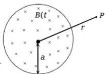
1. Is zero
2. Decreases as
3. Increases as r
4. Decreases as
A conducting wireframe is placed in a magnetic field that is directed into the paper. The magnetic field is increasing at a constant rate. The directions of induced current in wires AB and CD are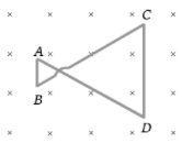
1. B to A and D to C
2. A to B and C to D
3. A to B and D to C
4. B to A and C to D
A square metallic wire loop of side 0.1 m and resistence of 1 is moved with a constant velocity in a magnetic field of 2 wb/ as shown in figure. The magnetic field is perpendicular to the plane of the loop, loop is connected to a network of resistances. What should be the velocity of loop so as to have a ssteady of 1mA in loop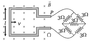
1. 1 cm/sec
2. 2 cm/sec
3. 3 cm/sec
4. 4 cm/sec
A rectangular loop with a sliding connector of length l = 1.0 m is situated in a uniform magnetic field B = 2T perpendicular to the plane of loop. Resistance of connector is r = 2. Two resistance of 6 and 3 are connected as shown in figure. The external force required to keep the connector moving with a constant velocity v = 2m/s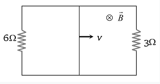
1. 6 N
2. 4 N
3. 2 N
4. 1 N
A wire cd of length l and mass m is sliding without friction on conducting rails ax and by as shown. The vertical rails are connected to each other with a resistance R between a and b. A uniform magnetic field B is applied perpendicular to the plane abcd such that cd moves with a constant velocity of 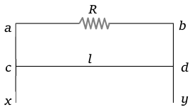
1.
2.
3.
4.
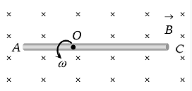
A conducting rod AC of length 4l is rotated about a point O in a uniform magnetic field  directed into the paper. AO = l and OC = 3l. Then
1.
2.
3.
4.
The network shown in the figure is a part of a complete circuit. If at a certain instant the current i is 5 A and is decreasing at the rate of A/s then is
1. 5 V
2. 10 V
3. 15 V
4. 20 V
A simple pendulum with a bob of mass m and conducting wire of length L swings under gravity through an angle . The earth's magnetic field component in the direction perpendicular to swing is B. Maximum potential difference induced across the pendulum is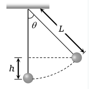
1.
2.
3.
4.
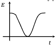
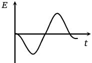
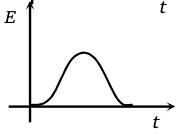
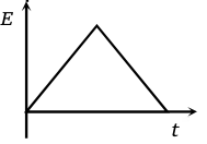
The variation of induced emf (E) with time (t) in a coil if a short bar magnet is moved along its axis with a constant velocity is best represented as
1. 
2. 
3. 
4. 
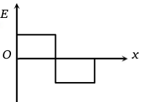
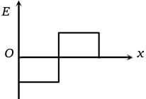
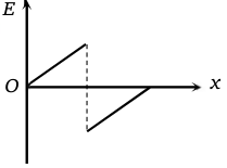
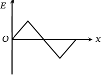
A rectangular loop is being pulled at a constant speed v, through a region of certain thickness d, in which a uniform magnetic field B is set up. The graph between position x of the right-hand edge of the loop and the induced emf E will be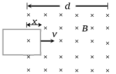
1. 
2. 
3. 
4. 
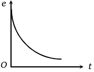
Switch S of the circuit shown in the figure. is closed at t = o. If e denotes the induced 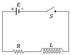
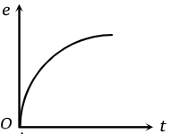
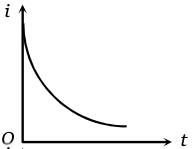
emf in L and i, the current flowing through the circuit at time t, which of the following graphs is correct
1. 
2. 
3. 
4. 