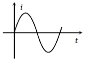
The potential difference V and the current i flowing through an instrument in an ac circuit of frequency f are given by V=5 cos t volts and I =2 sin
1.Zero
2.10 W
3.5 W
4. 2.5 W
| 1. | \(\frac{1}{100}~\text{sec}\) | 2. | \(\frac{1}{200}~\text{sec}\) |
| 3. | \(\frac{1}{300}~\text{sec}\) | 4. | \(\frac{1}{400}~\text{sec}\) |
An alternating current is given by the equation The r.m.s. current is given by
1.
2.
3.
4.
What will be the phase difference between virtual voltage and virtual current, when the current in the circuit is wattless
1.
2.
3. 1
4.
In a circuit L.C and R are connected in series with an alternating voltage source of
frequency f. The current leads the voltage by 45. The value of C is
1.
2.
3.
4.
One 10 V, 60 W bulb is to be connected to 100 V line. The required induction coil has self-inductance of value (f = 50 Hz)
1. 0.052 H
2. 2.42 H
3. 16.2 mH
4. 1.62 mH
In the circuit given below, what will be the reading of hte voltmeter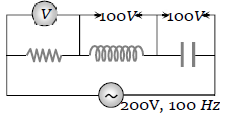
1. 300 V
2. 900 V
3. 200 V
4. 400 V
In the circuit shown below, what will be the readings of the voltmeter and ammeter 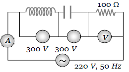
1. 800 V, 2A
2. 300 V, 2A
3. 220 V, 2.2 A
4. 100 V, 2A
In the circuit shown in figure neglecting source resistance, the voltmeter and ammeter reading will respectively, will be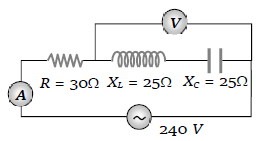
1. 0 V, 3A
2. 150 V, 3 A
3. 150 V, 6A
4. 0 V, 8A
A virtual current of 4A and 50 Hz flow in an ac circuit containing a coil. The power consumed in hte coil is 240 W. If the virtual voltage across te coil is 100 V its inductance will be
1.
2.
3.
4.
For a series RLC circuit R=X=2Xc. The impedance of the circuit and phase difference (between) V and i will be
1.
2.
3.
4.
In the adjoining ac circuit, the voltmeter whose reading will be zero at resonance is 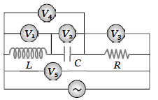
1.
2.
3.
4.
In the adjoining figure, the impedance of the circuit will be 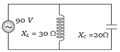
1. 120 ohm
2. 50 ohm
3. 60 ohm
4. 90 ohm
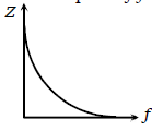
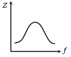
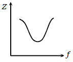
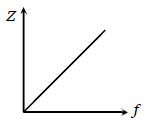
Which one of the following curves represents the variation of impedance (Z) with frequency f in series LCR circuit
1. 
2. 
3. 
4. 
The figure shows variation of R, and with frequency f in a series L, C, R circuit. Then for what frequency point, the circuit is inductive 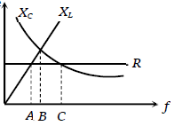
1. A
2. B
3. C
4. All points
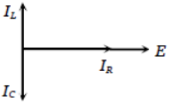
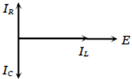
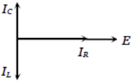
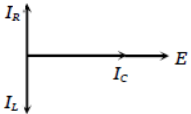
An alternating emf is applied across a parallel combination of a resistance R, capacitance C and an inductance L. If , Il,Ic are the currents through R, L and C respectively, then the diagram which correctly represents, the phase relationship among Tr, IL,Ic and source emf E, is given by
1. 
2. 
3. 
4. 
The output current versus time curve of a rectifier is shown in the figure. The average vale of output current in this case is
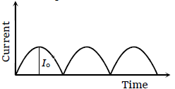
1. 0
2.
3.
4.
When an ac source of e.m.f. e= sin(100) is connected across a circuit, the phase difference between the e.m.f. e and the current in the circuit is observed to be /4, as shown in the diagram. If the circuit consists possibly only of RC or LC in series, find the relationship between the two elements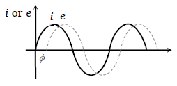
1.
2.
3.
4.
Two sinusoidal voltages of the same frequency are shown in the diagram. What is the frequency are shown in the diagram. What is the frequency, and the phase relationship between the voltages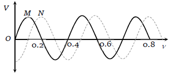
Frequency in Hz Phase lead of N
over M in radians
1. 0.4
2. 2.5
3. 2.5
4. 2.5
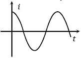
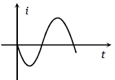
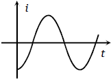
The voltage across a pure inductor is represented by the following diagram. Which one of the following diagrams will represent the current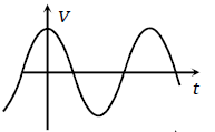
1. 
2. 
3. 
4. 