In Young's double-slit experiment, slits are separated by 0.5 mm and the screen is placed 150 cm away. A beam of light consisting of two wavelengths, 650 nm and 520 nm, is used to obtain interference fringes on the screen. The least distance from the common central maximum to the point where the bright fringes due to both the wavelengths coincide is
1. 7.7 mm
2. 9.75 mm
3. 15.6 mm
4. 1.56 mm
Two coherent point sources are separated by a small distance d as shown. The fringes obtained on the screen will be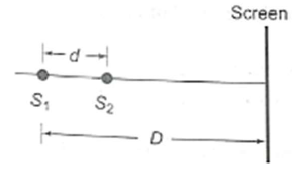
1. Points
2. Straight lines
3. Semi-circle
4. Concentric circles
In Young's double-slit experiment using monochromatic light of wavelength the path difference (in terms of an integer n) corresponding to any point having half the peak intensity is
1.
2.
3.
4.
In the adjacent diagram, CP represents a wavefront and AO and BP, the corresponding two rays. Find the condition of θ for constructive interference at P between the ray BP
and reflected ray OP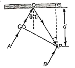
(1) cosθ=
(2) cosθ=
(3) secθ−cosθ=
(4) secθ−cosθ=
In the ideal double-slit experiment when a glass-plate (refractive index 1.5) of thickness t is introduced in the path of one of the interfering beams (wavelength ), the intensity at the position where the central maximum occurred previously remains unchanged. The minimum thickness of the glass-plate is
1. 2
2. 2/3
3. /3
4.
In Young's double-slit experiment, 12 fringes are observed to be formed in a certain segment of the screen when the light of wavelength 600 nm is used. If the wavelength of light is changed to 400 nm, the number of fringes observed in the same segment of the screen is given by
1. 12
2. 18
3. 24
4. 30
In Young's double-slit experiment, how many maxima can be obtained on a screen (including the central maximum) on both sides of the central fringe if ?
(1) 12
(2) 7
(3) 18
(4) 4
Fig. shows a transparent slab of length 1 m placed in air whose refractive index in the x-direction varies as . The optical path length of the ray R inside the slab will be
(1) 1 m
(2) (2/3) m
(3) (3/2) m
(4) m
Plane waves are of wavelength incident on a pair of slits at angle , as shown in fig. At what value of , is the first order minimum located?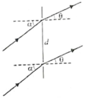
1.
2.
3.
4.
In Young's double-slit experiment, a point P on the central bright fringe is such that the intensity the point P is 1/4 time the maximum intensity. The distance between the slits is d and the wavelength is . Then angular separation of point P is
1.
2.
3.
4.
In fig. S is a monochromatic source emitting light of wavelength = 500nm and thin lens of focal length 0.10 m is cut into identical halves. The two halves are placed symmetrically about the central axis SO with a gap of d = 0.5 mm. The distance of the lens from S is 0.15m and that from O is 1.30 m. If the third intensity maximum occurs at a point A on the screen (perpendicular to SO), find the distance OA.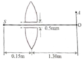
1. 0.5 mm
2. 1.0 mm
3. 1.5 mm
4. 2.0 mm
In a diffraction pattern due to a single slit of width 'a', the first minimum is observed at an angle 30 when the light of wavelength 5000 A is incident on the slit. The first secondary maximum is observed at an angle of
1.
2.
3.
4.
Two polaroids are placed in the path of the unpolarized beam of intensity such that no light is emitted from the second polaroid. If a third polaroid whose polarization axis makes an angle with the polarization axis of the first polaroid, is placed between these polaroids then the intensity of light emerging from the last Polaroid will be
1.
2.
3.
4.
The graph showing the dependence of the intensity of transmitted light on the angle between polarizer and analyzer is:
| 1. | 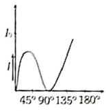 |
2. | 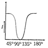 |
| 3. | 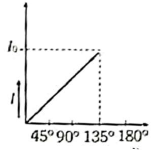 |
4. | 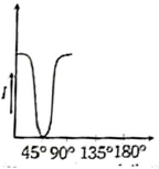 |
In Young's double-slit experiment (slit distance d) monochromatic light of wavelength is used and the figure pattern observed at a distance L from the slits. The angular position of the bright fringes are
1.
2.
3.
4.
If two waves represented by interfere at a point, the amplitude of the resulting wave will be about
1. 7
2. 6
3. 5
4. 3.5
Two slits in Young's experiment have widths in the ratio 1:25. The ratio of intensity at the maximum and minimum in the interference pattern, is
1. 121/49
2. 29/121
3. 4/9
4. 9/4
Spherical wavefronts shown in the figure, strike a plane mirror (as shown in the figure below). Reflected wavefronts will be shown in:
| 1. |  |
2. |  |
| 3. |  |
4. |  |