In the circuit shown in the figure below, the current supplied by the battery is:

1. \(2~\text A\)
2. \(1~\text A\)
3. \(0.5~\text A\)
4. \(0.4~\text A\)

1. \(2~\text A\)
2. \(1~\text A\)
3. \(0.5~\text A\)
4. \(0.4~\text A\)
If a resistance coil is made by joining in parallel two resistances each of 20. An emf of 2V is applied across this coil for 100 seconds. The heat produced in the coil is
(1) 20 J
(2) 10 J
(3) 40 J
(4) 80 J
The equivalent resistance across AB is :
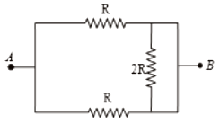
1. 2R
2. R/2
3. 4R/3
4. 3R/2
The equivalent resistance between points \(A\) and \(B\) in the circuit shown in the figure is:

| 1. | \(6R\) | 2. | \(4R\) |
| 3. | \(2R\) | 4. | \(R\) |
In the circuit shown in the figure, the effective resistance between A and B is:
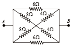
1. 2
2. 4
3. 6
4. 8
For the circuit shown in the figure, the value of R must be
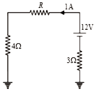
1. 3
2. 4
3. 5
4. 6
Current I as shown in the circuit will be
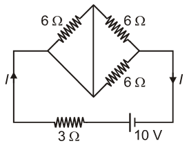
1. 10 A
2.
3.
4.
The current through the 5 resistor is
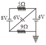
(1) 3.2A
(2) 2.8A
(3) 0.8A
(4) 0.2A
In the figure, a carbon resistor has bands of different colours on its body as mentioned in the figure. The value of the resistance is:
1. \(2.2\) k\(\Omega\)
2. \(3.3\) k\(\Omega\)
3. \(5.6\) k\(\Omega\)
4. \(9.1\) k\(\Omega\)


