

For the circuit shown in figure below, the ammeter reads 1.6 A and ammeter read 0.4 A If is angular frequency and is frequency of ac, then


If the reading of and are 100 V each, the reading of is
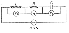
1. 0 V
2. 100 V
3. 200 V
4. Cannot be determined by given information
Given that the current \(i_1=3A \sin \omega t\) and the current \(i_2=4A \cos \omega t,\) what will be the expression for the current \(i_3\)?

1. \(5 A \sin \left(\omega t+53^{\circ}\right) \)
2. \(5 A \sin \left(\omega t+37^{\circ}\right) \)
3. \(5 A \sin \left(\omega t+45^{\circ}\right) \)
4. \( 5 A \sin \left(\omega t+30^{\circ}\right)\)


A capacitor of capacitance \(1~\mu\text{F}\) is charged to a potential of \(1\) V. It is connected in parallel to an inductor of inductance \(10^{-3}~\text{H}\).
What is the value of the maximum current that will flow in the circuit?
1. \(\sqrt{1000}~\text{mA}\)
2. \(1~\text{mA}\)
3. \(1~\mu\text{F}\)
4. \(1000~\text{mA}\)
In a box \(Z\) of unknown elements (\(L\) or \(R\) or any other combination), an ac voltage \(E = E_0 \sin(\omega t + \phi)\) is applied and the current in the circuit is found to be \(I = I_0 \sin\left(\omega t + \phi +\frac{\pi}{4}\right)\). The unknown elements in the box could be:

| 1. | Only the capacitor |
| 2. | Inductor and resistor both |
| 3. | Either capacitor, resistor, and an inductor or only capacitor and resistor |
| 4. | Only the resistor |
In the transformer shown in the figure, the ratio of the number of turns of primary to the secondary is . If a battery of emf 10 V is connected across primary, then induced current through the load of 10 k in the secondary is
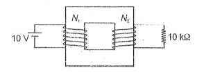


| 1. | \(2500\) W | 2. | \(250\) W |
| 3. | \(5000\) W | 4. | \(4000\) W |
EMF induced in the secondary coil of an ideal transformer does not depend upon
1. EMF in the primary coil
2. Frequency of source
3. Ratio of number of turns
4. Both (1) & (3)
The phase difference between emf and current through the choke coil maybe
1. 0
2. 85
3. 45
4. 30


1. \(\dfrac{\pi }{\sqrt{3}}~\text{H}\)
2. \(100~\text{H}\)
3. \(\dfrac{\sqrt{2}}{\pi }~\text{H}\)
4. \(\dfrac{\sqrt{3}}{\pi }~\text{H}\)
© 2026 GoodEd Technologies Pvt. Ltd.