
 Q. No.
Phasor diagram for a circuit is given below. The circuit is-

1. Purely capacitive circuit
2. Purely inductive circuit
3. Purely resistive circuit
4. RC circuit


Graph given below shows variation of voltage, current and flux for a magnetisation-demagnetisation cycle for an inductor. One of the correct conclusion out of the graph below can be:
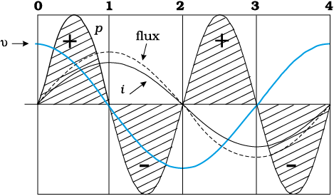
1. Voltage leads current
2. Current leads voltage
3. Voltage and current are in phase
4. Sometimes current leads sometimes voltage leads
Phasor diagram given below represents which circuit?

1. Purely capacitive circuit
2. Purely inductive circuit
3. Purely resistive circuit
4. RC circuit


Graph given below shows variation of voltage, current and charge for a charging-discharging cycle for a capacitor. Then -
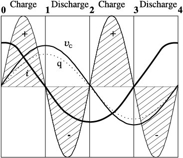
1. Voltage leads current
2. Current leads voltage
3. Voltage and current are in phase
4. Sometimes current leads sometimes voltage leads
The phasor diagram given below represents a series LCR circuit. The circuit is predominantly-

1. Capacitive
2. Inductive
3. Resistive
4. All of the above
In the phasor diagram given below, phase difference between current and voltage, . Then the circuit is-

1. Purely capacitive circuit
2. Purely inductive circuit
3. Purely resistive circuit
4. LCR circuit


Figure shows the variation of peak current im with angular frequency for a LCR series circuit for different values of resistor R. Then the resonant frequency is-
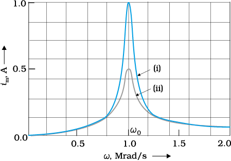
1.
2.
3.
4.
The graph given below shows the variation of voltage and current with phase for an AC circuit. The circuit is:

1. Purely capacitive circuit
2. Purely inductive circuit
3. Purely resistive circuit
4. RC circuit
Graph given below shows variation of voltage and current with phase for an AC circuit. Then the circuit is predominantly-

1. Capacitive
2. Inductive
3. Resistive
4. All of the above


Graph given below shows variation of voltage and current with phase for an AC circuit. What is the phase difference between current(i) and voltage(v)?

1. 0
2.
3.
4.
© 2026 GoodEd Technologies Pvt. Ltd.