
 Q. No.
Two circular coils can be arranged in any of the three situations shown in the figure. Their mutual inductance will be

1. Maximum in situation (A)
2. Maximum in situation (B)
3. Maximum in situation (C)
4. The same in all situations


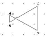
A conductor ABOCD moves along its bisector with a velocity of 1 m/s through a perpendicular magnetic field of 1 wb/m2, as shown in fig. If all the four sides are of 1m length each, then the induced emf between points A and D is

1. 0
2. 1.41 volt
3. 0.71 volt
4. None of the above
A wire cd of length l and mass m is sliding without friction on conducting rails ax and by as shown. The vertical rails are connected to each other with a resistance R between a and b. A uniform magnetic field B is applied perpendicular to the plane abcd such that cd moves with a constant velocity of

1.
2.
3.
4.


The figure shows three circuits with identical batteries, inductors, and resistors. Rank the circuits according to the current, in descending order, through the battery \((i)\) just after the switch is closed and \((ii)\) a long time later:

| 1. | \((i)~ i_2>i_3>i_1\left(i_1=0\right) (ii) ~i_2>i_3>i_1\) |
| 2. | \((i)~ i_2<i_3<i_1\left(i_1 \neq 0\right) (ii)~ i_2>i_3>i_1\) |
| 3. | \((i) ~i_2=i_3=i_1\left(i_1=0\right) (ii)~ i_2<i_3<i_1\) |
| 4. | \((i)~ i_2=i_3>i_1\left(i_1 \neq 0\right) (ii) ~i_2>i_3>i_1\) |
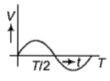
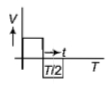
The variation of induced emf (E) with time (t) in a coil if a short bar magnet is moved along its axis with a constant velocity is best represented as:

| 1. |  |
2. |  |
| 3. |  |
4. |  |
Some magnetic flux is changed from a coil of resistance 10 ohm. As a result an induced current is developed in it, which varies with time as shown in figure. The magnitude of change in flux through the coil in webers is

1. 2
2. 4
3. 6
4. None of these


Figure (i) shows a conducting loop being pulled out of a magnetic field with a speed v. Which of the four plots shown in figure (ii) may represent the power delivered by the pulling agent as a function of the speed v

1. a
2. b
3. c
4. d
A conducting wireframe is placed in a magnetic field that is directed into the paper. The magnetic field is increasing at a constant rate. The directions of induced current in wires AB and CD are
1. B to A and D to C
2. A to B and C to D
3. A to B and D to C
4. B to A and C to D
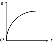
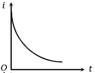
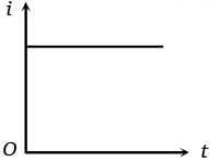
Switch S of the circuit shown in the figure. is closed at t = o. If e denotes the induced
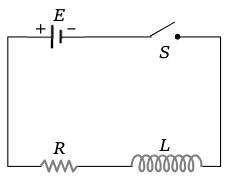
emf in L and i, the current flowing through the circuit at time t, which of the following graphs is correct
1. 
2. 
3. 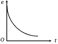
4. 


The current (I) in the inductance is varying with time according to the plot shown in figure.

Which one of the following is the correct variation of voltage with time in the coil?
1. 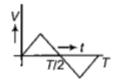
2. 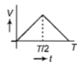
3. 
4. 
© 2026 GoodEd Technologies Pvt. Ltd.