 Q. No.
\(220 ~\mathrm{V}\), \(50~\mathrm{Hz}\), AC source is connected to an inductance of \(0.2~\mathrm{H}\) and a resistance of \(20\) \(\Omega\) in series. What is the current in the circuit?
1. \(3.33~\mathrm{A}\)
2. \(33.3~\mathrm{A}\)
3. \(5\mathrm{A}\)
4. \(10\mathrm{~A}\)
2. \(33.3~\mathrm{A}\)
3. \(5\mathrm{A}\)
4. \(10\mathrm{~A}\)


Voltage across each elements of a series LCR
circuit are given by VL= 60V, VC= 20V,VR= 30V
Find out source voltage.
1. 50V
2. 100V
3. 150V
4. 200V
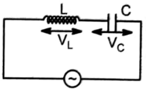
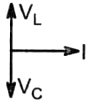
The current I, potential difference VL across the inductor and potential difference VC across the capacitor in the circuit as shown in the figure are best represented vectorially as:
1. 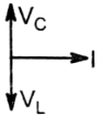 2.
2. 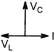
3. 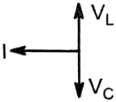 4.
4. 


Resonance occurs in a series L-C-R circuit when the frequency of the applied e.m.f. is 1000 Hz. Then:
1. when f=900 Hz, the circuit behaves as a capacitive circuit
2. the impendence of the circuit is maximum at f=1000 Hz
3. at resonance the voltages across L and current in C differ in phase by 180
4. if the value of C is doubled resonance occurs at f=2000 Hz
If we change the value of \(R,\) then:

| 1. | voltage does not change on \(L\) |
| 2. | voltage does not change on \(LC\) combination |
| 3. | voltage does not change on \(C\) |
| 4. | voltage changes on \(LC\) combination |
In an AC circuit, the emf (e) and the current (I) at any instant are given respectively by
e = E0sint
I = I0sin
The average power in the circuit over one cycle of AC is:
1.
2.
3.
4.


The power dissipated in an L-C-R series circuit connected to an AC source of emf E is:
In the given circuit, the reading of voltmeter V1 and V2 are 300 V each. The reading of the voltmeter V3 and ammeter A are respectively:

1. 150 V, 2.2 A
2. 220 V, 2.2 A
3. 220 V, 2.0 A
4. 100 V, 2.0 A
An AC voltage is applied to a resistance R and an inductor L in series. If R and the inductive reactance are both equal to 3 , the phase difference between the applied voltage and the current in the circuit is:
1.
2.
3. zero
4.


| 1. | \(100~\text{mA}\) | 2. | \(200~\text{mA}\) |
| 3. | \(20~\text{mA}\) | 4. | \(10~\text{mA}\) |
© 2026 GoodEd Technologies Pvt. Ltd.