 Q. No.
A conducting wireframe is placed in a magnetic field that is directed into the paper. The magnetic field is increasing at a constant rate. The directions of induced current in wires AB and CD are

(1) B to A and D to C
(2) A to B and C to D
(3) A to B and D to C
(4) B to A and C to D


A conductor ABOCD moves along its bisector with a velocity of 11 m/s through a perpendicular magnetic field of 1 wb/m21 wb/m2, as shown in fig. If all the four sides are of 11 m length each, then the induced emf between points A and D is:

1. 00
2. 1.411.41 volt
3. 0.710.71 volt
4. None of the above
A conducting rod PQ of length L = 1.0 m is moving with a uniform speed v = 2 m/s in a uniform magnetic field B = 4.0 T directed into the paper. A capacitor of capacity C = 10 μF is connected as shown in figure. Then

(1) qA = + 80 μC and qB = – 80 μC
(2) qA = – 80 μC and qB = + 80 μC
(3) qA = 0 = qB
(4) Charge stored in the capacitor increases exponentially with time


The resistance in the following circuit is increased at a particular instant. At this instant the value of resistance is 10Ω. The current in the circuit will be now

(1) i = 0.5 A
(2) i > 0.5 A
(3) i < 0.5 A
(4) i = 0
A highly conducting ring of radius R is perpendicular to and concentric with the axis of a long solenoid as shown in fig. The ring has a narrow gap of width d in its circumference. The solenoid has a cross-sectional area A and a uniform internal field of magnitude B0. Now beginning at t = 0, the solenoid current is steadily increased so that the field magnitude at any time t is given by B(t) = B0 + αt where α > 0. Assuming that no charge can flow across the gap, the end of the ring which has an excess of positive charge and the magnitude of induced e.m.f. in the ring are respectively

(1) X, Aα
(2) X πR2α
(3) Y, πA2α
(4) Y, πR2α
A wire cd of length ll and mass mm is sliding without friction on conducting rails axax and byby as shown. The vertical rails are connected to each other with a resistance RR between aa and bb. A uniform magnetic field BB is applied perpendicular to the plane abcdabcd such that cdcd moves with a constant velocity of:

| 1. | mgRBlmgRBl | 2. | mgRB2l2mgRB2l2 |
| 3. | mgRB3l3mgRB3l3 | 4. | mgRB2lmgRB2l |


A conducting rod ACAC of length 4l4l is rotated about point OO in a uniform magnetic field →B→B directed into the paper. If AO=lAO=l and OC=3lOC=3l, then:
1. VA−VO=Bωl22VA−VO=Bωl22
2. VO−VC=72Bωl2VO−VC=72Bωl2
3. VA−VC=4Bωl2VA−VC=4Bωl2
4. VC−VO=92Bωl2VC−VO=92Bωl2

The network shown in the figure is a part of a complete circuit. If at a certain instant the current i is 5 A and is decreasing at the rate of 103 A/s then VB – VA is

(1) 5 V
(2) 10 V
(3) 15 V
(4) 20 V
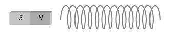
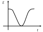
The variation of induced emf (E) with time (t) in a coil if a short bar magnet is moved along its axis with a constant velocity is best represented as
(1)
(2)

(3)

(4)


A loop abcd is moved across the pole pieces of a magnet as shown in fig. with a constant speed v. When the edge ab of the loop enters the pole pieces at time t = 0 sec. , which one of the following graphs represents correctly the induced emf in the coil?

(1)

(2)

(3)

(4)

© 2025 GoodEd Technologies Pvt. Ltd.