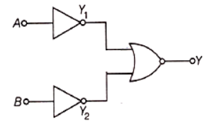
To get output 1 for the following circuit, the correct choice for the input is:
 1. A = 1, B = 0, C = 0
2. A = 1, B = 1, C = 0
3. A = 1, B = 0, C = 1
4. A = 0, B = 1, C = 0

2. A = 1, B = 1, C = 0
3. A = 1, B = 0, C = 1
4. A = 0, B = 1, C = 0

To unlock all the explanations of 14 chapters you need to be enrolled in MasterClass Course.

To unlock all the explanations of 14 chapters you need to be enrolled in MasterClass Course.
2. 10-1A
3. 10-3A
4. 0A

To unlock all the explanations of 14 chapters you need to be enrolled in MasterClass Course.

To unlock all the explanations of 14 chapters you need to be enrolled in MasterClass Course.

2. NAND
3. AND
4. NOR

To unlock all the explanations of 14 chapters you need to be enrolled in MasterClass Course.

To unlock all the explanations of 14 chapters you need to be enrolled in MasterClass Course.
2. Holes are minority carriers and pentavalent atoms are dopants.
3. Holes are majority carriers and trivalent atoms are dopants.
4. Electrons are majority carriers and trivalent atoms are dopants.

To unlock all the explanations of 14 chapters you need to be enrolled in MasterClass Course.

To unlock all the explanations of 14 chapters you need to be enrolled in MasterClass Course.
The output(X) of the logic circuit shown in figure will be:

1. X =
2. X = A.B
3. X =
4. X =

To unlock all the explanations of 14 chapters you need to be enrolled in MasterClass Course.

To unlock all the explanations of 14 chapters you need to be enrolled in MasterClass Course.
Two ideal diodes are connected to a battery as shown in the circuit. The current supplied by the battery is:
1. 0.75 A
2. zero
3. 0.25 A
4. 0.5 A

To unlock all the explanations of 14 chapters you need to be enrolled in MasterClass Course.

To unlock all the explanations of 14 chapters you need to be enrolled in MasterClass Course.
C and Si both have the same lattice structure, having 4 bonding electrons in each. However, C is an insulator whereas Si is an intrinsic semiconductor. This is because:
1. in the case of C, the valence band is not completely filled at absolute zero temperature.
2. in the case of C, the conduction band is partly filled even at absolutely zero temperature.
3. the four bonding electrons in the case of C lie in the second orbit, whereas in the case of Si, they lie in the third.
4. the four bonding electrons in the case of C lie in the third orbit, whereas for Si, they lie in the fourth orbit.

To unlock all the explanations of 14 chapters you need to be enrolled in MasterClass Course.

To unlock all the explanations of 14 chapters you need to be enrolled in MasterClass Course.
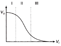
Transfer characteristic [output voltage () vs input voltage ()] for a base biased transistor in CE configurations as shown in the figure. For using the transistor as a switch, it is used:

1. In region III
2. Both in the region (I) and (III)
3. In region II
4. In region I

To unlock all the explanations of 14 chapters you need to be enrolled in MasterClass Course.

To unlock all the explanations of 14 chapters you need to be enrolled in MasterClass Course.
The figure shows a logic circuit with two inputs A and B and the output C. The voltage waveforms across A, B, and C are as given. The logic circuit gate is:
1. OR gate
2. NOR gate
3. AND gate
4. NAND gate

To unlock all the explanations of 14 chapters you need to be enrolled in MasterClass Course.

To unlock all the explanations of 14 chapters you need to be enrolled in MasterClass Course.

Pick out which ones are for AND, NAND, and NOT gates, respectively.
1. (i), (iv), and (iii)
2. (ii), (iii), and (iv)
3. (ii), (iv), and (iii)
4. (ii), (iv), and (i)

To unlock all the explanations of 14 chapters you need to be enrolled in MasterClass Course.

To unlock all the explanations of 14 chapters you need to be enrolled in MasterClass Course.


