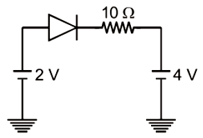
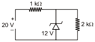
The following configuration of the logic gate is equivalent to

1. NAND gate
2. XOR gate
3. OR gate
4. NOR gate
Three ideal diodes are connected to the battery as shown in the circuit. The current supplied by the battery is:
1. zero
2. \(4~\text{A}\)
3. \(2~\text{A}\)
4. \(6~\text{A}\)
If a small amount of aluminium is added to the silicon crystal:
| 1. | its resistance decreases. |
| 2. | it becomes a \(\mathrm{p\text-}\)type semiconductor. |
| 3. | there will be fewer free electrons than holes in the semiconductor. |
| 4. | All of these are correct. |
| 1. | the depletion region becomes thick. |
| 2. | the \(\mathrm{p}\text-\)side is at a higher potential than \(\mathrm{n\text-}\)side. |
| 3. | the current flowing is zero. |
| 4. | the effective resistance is of the order of \(10^6 ~\Omega\). |
When a transistor is used as a switch it is in:
1. Active state
2. Cut off state
3. Saturation state
4. Both cut off state and saturation state are possible
The current through an ideal p-n junction diode shown in the circuit will be:

1. 5 A
2. 0.2 A
3. 0.6 A
4. zero


1. 36 mW
2. 12 mW
3. 144 mW
4. 64 mW
The given electrical network is equivalent to
1. AND gate
2. OR gate
3. NOR gate
4. NOT gate
Which one of the following represents forward biased circuit?
1.
2.
3.
4.
What is the output Y in the following circuit, when all the three inputs A,B,C are first 0 and then 1 ?
1. 0,1
2. 0,0
3. 1,0
4. 1,1


