Three ideal diodes are connected to the battery as shown in the circuit. The current supplied by the battery is:
1. zero
2. \(4~\text{A}\)
3. \(2~\text{A}\)
4. \(6~\text{A}\)
A transistor is operated in common emitter configuration at When base current is changed from 10mA to 30mA, it produces a change in emitter current from 2A to 4A, the current amplification factor is
1. 100
2. 99
3. 10
4. 9
| 1. | the depletion region becomes thick. |
| 2. | the \(\mathrm{p}\text-\)side is at a higher potential than \(\mathrm{n\text-}\)side. |
| 3. | the current flowing is zero. |
| 4. | the effective resistance is of the order of \(10^6 ~\Omega\). |
When a transistor is used as a switch it is in:
1. Active state
2. Cut off state
3. Saturation state
4. Both cut off state and saturation state are possible
The conductivity of an n-type semiconductor whose density of conduction electrons is , Density of holes is , Mobility of conduction electrons is and Mobility of holes is will be
1.
2.
3.
4.
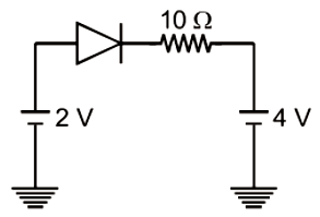
The current through an ideal p-n junction diode shown in the circuit will be:

1. 5 A
2. 0.2 A
3. 0.6 A
4. zero


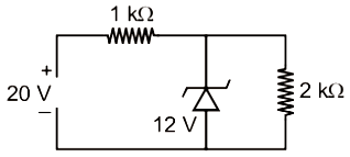
1. 36 mW
2. 12 mW
3. 144 mW
4. 64 mW
The given electrical network is equivalent to
1. AND gate
2. OR gate
3. NOR gate
4. NOT gate
In a common-emitter transistor amplifier, the audio signal voltage across the collector is 3 V. The resistance of the collector is 3 k. If the current gain is 100 and the base resistance is 2 k, the voltage and power gain of the amplifier are:
1. 200 and 1000
2. 15 and 200
3. 150 and 15000
4. 20 and 2000
The given circuit has two ideal diodes connected as shown in the figure below. The current flowing through the resistance \(R_1\) will be
1. \( 2.5\text{ A}\)
2. \( 10\text{ A}\)
3. \(1.43\text{ A}\)
4. \(3.13\text{ A}\)


