
 Q. No.
In an electrical circuit R, L, C, and an AC voltage source are all connected in series. When L is removed from the circuit, the phase difference between the voltage and the current in the circuit is If instead, C is removed from the circuit, the phase difference is again The power factor of the circuit is
1. 1/2
2. 1/
3. 1
4.
एक विद्युत परिपथ में R, L, C, और एक AC वोल्टेज स्रोत सभी श्रेणीक्रम में जुड़े हुए हैं। जब L को परिपथ से हटा दिया जाता है, तब वोल्टता और धारा के बीच का कलांतर है। यदि इसके विपरीत, C को परिपथ से हटा दिया जाता है, तब कलांतर पुनः है। परिपथ का शक्ति गुणांक है-
1. 1/2
2. 1/
3. 1
4.


In a coil of resistance 10, the induced
current developed by changing magnetic
flux through it is shown in the figure as a
function of time. The magnitude of change
in flux through the coil in weber is-

(a) 8
(b) 2
(c)6
(d)4
प्रतिरोध 10 की एक कुंडली में, समय के फलन के रूप में इसके माध्यम में चुंबकीय फ्लक्स में परिवर्तन करने पर एक प्रेरित धारा उत्पन्न होती है जैसा कि चित्र में दर्शाया गया है। कुंडली के माध्यम से फ्लक्स परिवर्तन का परिमाण
वेबर में है-
(a) 8
(b) 2
(c)6
(d)4
An AC voltage is applied to a resistance R and an inductor L in series. If R and the inductive reactance are both equal to , the phase difference between the applied voltage and the current in the circuit is
(a) (b)
(c) zero (d)
एक प्रत्यावर्ती धारा वोल्टता को श्रेणीक्रम में एक प्रतिरोध R और एक प्रेरक L पर लागू किया जाता है। यदि R और प्रेरकीय प्रतिघात दोनों के समान हैं, परिपथ में लागू वोल्टता और धारा के बीच का कलांतर है
(a) (b)
(c) शून्य (d)


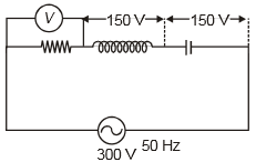
In the given circuit the reading of voltmeter are 300V each. The reading to the voltmeter and ammeter A are respectively :

(a) 150V, 2.2A
(b) 220V, 2.2A
(c) 220V, 2.0A
(d) 100V, 2.0A
दिए गए परिपथ में, वोल्टमीटर प्रत्येक का पाठ्यांक 300V हैं। वोल्टमीटर और एमीटर के पाठ्यांक क्रमशः हैं:
(a) 150V, 2.2A
(b) 220V, 2.2A
(c) 220V, 2.0A
(d) 100V, 2.0A
In a series LCR circuit, resistance R = 10Ω and the impedance Z = 20Ω. The phase difference between the current and the voltage is
(1) 30°
(2) 45°
(3) 60°
(4) 90°
एक श्रेणी LCR परिपथ में, प्रतिरोध R = 10Ω और प्रतिबाधा Z = 20Ω है। धारा और वोल्टता के बीच कलांतर है:
(1) 30°
(2) 45°
(3) 60°
(4) 90°
In the circuit given below, the reading of the voltmeter V will be

1. 0
2. 100 V
3. 200 V
4. 300 V
नीचे दिए गए परिपथ में, वोल्ट्मीटर V का पाठ्यांक होगा
1. 0
2. 100V
3. 200V
4. 300V


If \(\begin{array}{ccc}{\mathrm{X_{L}}}&{=}&{\mathrm{X_{C}}}\end{array}\) then the reading of ideal voltmeter is :
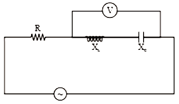
1. \(\begin{array}{ccccc}\mathrm{V}&=&\mathrm{V}_\mathrm{L}&\cdot&\mathrm{V}_\mathrm{C}\end{array}\)
2. \(\mathrm{V}=\sqrt{V_{\mathrm{R}}^{2}+V_{\mathrm{L}}^{2}}\)
3. \(\begin{array}{rcl}\mathrm{V}&=&\sqrt{\mathrm{V}_{\mathrm{R}}^{2}\quad+\quad\mathrm{V}_{\mathrm{L}}\quad-\quad\mathrm{V}_{\mathrm{C}}^{2}}\end{array}\)
4. zero
यदि \(\begin{array}{ccc}{\mathrm{X_{L}}}&{=}&{\mathrm{X_{C}}}\end{array}\) है, तब आदर्श वोल्टमीटर का पाठ्यांक है:

1. \(\begin{array}{ccccc}\mathrm{V}&=&\mathrm{V}_\mathrm{L}&\cdot&\mathrm{V}_\mathrm{C}\end{array}\)
2. \(\mathrm{V}=\sqrt{V_{\mathrm{R}}^{2}+V_{\mathrm{L}}^{2}}\)
3. \(\begin{array}{rcl}\mathrm{V}&=&\sqrt{\mathrm{V}_{\mathrm{R}}^{2}\quad+\quad\mathrm{V}_{\mathrm{L}}\quad-\quad\mathrm{V}_{\mathrm{C}}^{2}}\end{array}\)
4. शून्य
The diagram shows a capacitor C and a resistor R connected in series to an ac source. V1 and V2 are voltmeters and A is an ammeter:

Consider now the following statements
I. Readings in A and V2 are always in phase
II. Reading in V1 is ahead in phase with reading in V2
III. Readings in A and V1 are always in phase
Which of these statements is/are correct?
(1) I only
(2) II only
(3) I and II only
(4) II and III only
आरेख में एक संधारित्र C और प्रतिरोध R, ac स्त्रोत के साथ श्रेणीक्रम में जुड़े हुए दर्शाए गए है। V1 और V2 वोल्टमीटर हैं और A ऐमीटर है:
अब निम्नलिखित कथनों पर विचार कीजिए -
I. A और V2 में पाठ्यांक सदैव कला में हैं।
II. V1 में पाठ्यांक, V2 के पाठ्यांक से कला में आगे है।
III. A और V1 में पाठ्यांक सदैव कला में हैं।
निम्न में से कौन-सा कथन सही है/हैं?
(1) केवल I
(2) केवल II
(3) केवल I और II
(4) केवल II और III
An ac source of variable frequency f is connected to an LCR series circuit. Which one of the graphs in the figure represents the variation of the current I in the circuit with frequency f :
(1)

(2)

(3)

(4)

एक परिवर्ती आवृत्ति f का एक प्रत्यावर्ती स्रोत श्रेणी LCR परिपथ से जुड़ा हुआ है। आकृति में कौन सा आलेख आवृत्ति f के साथ परिपथ में धारा I के परिवर्तन को दर्शाता है:
(1)
(2)
(3)
(4)


A constant voltage at different frequencies is applied across a capacitance C as shown in the figure. Which of the following graphs

Correctly depicts the variation of current with frequency?
(1)

(2)

(3)

(4)

विभिन्न आवृत्तियों पर एक नियत वोल्टता एक संधारित्र C के सिरों पर लागू की जाती है जैसा कि चित्र में दर्शाया गया है। निम्नलिखित में से कौन सा ग्राफ सही तरह से आवृत्ति के साथ धारा के परिवर्तन को दर्शाता है?
*Signal generator - एकल जनित्र
(1)
(2)
(3)
(4)
© 2026 GoodEd Technologies Pvt. Ltd.